Unveiling the Essence of Flow Diagrams and Functional Decomposition in Advanced ECE & EEE Projects
Introduction:
In the realm of Advanced Electronics and Electrical Engineering (ECE & EEE) projects, the utilization of flow diagrams and functional decomposition serves as a cornerstone for conceptualizing, designing, and implementing complex systems. This blog delves into the significance of these methodologies, exploring their applications, benefits, and impact within the field of ECE & EEE projects.
Understanding Flow Diagrams:
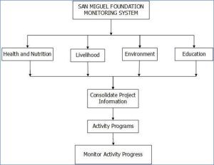
Flow diagrams, also known as flowcharts, are graphical representations of processes or systems that illustrate the sequence of steps, actions, or events involved. In ECE & EEE projects, flow diagrams provide a visual framework for understanding system functionality, identifying dependencies, and analyzing process flow. From circuit design to system integration, flow diagrams play a pivotal role in elucidating the structure and operation of complex electronic and electrical systems.

Applications of Flow Diagrams in ECE & EEE Projects:
Flow diagrams find widespread applications across various stages of ECE & EEE projects, including:
- System Design: Flow diagrams aid in conceptualizing system architecture, defining input-output relationships, and specifying component interactions.
- Circuit Design: In circuit design, flow diagrams depict the flow of signals, data, and control signals, facilitating the visualization of circuit operation and troubleshooting.
- Software Development: For projects involving embedded systems or firmware development, flow diagrams help map out software algorithms, control logic, and program execution flow.
- System Integration: During system integration, flow diagrams assist in coordinating subsystems, verifying system behavior, and diagnosing integration issues.
- Testing and Validation: Flow diagrams serve as a reference for designing test cases, validating system functionality, and identifying areas for improvement or optimization.

Benefits of Flow Diagrams in ECE & EEE Projects:
The utilization of flow diagrams offers several benefits in ECE & EEE projects, including:
- Visual Clarity: Flow diagrams provide a clear and intuitive representation of system structure and operation, enhancing understanding and communication among project stakeholders.
- Error Detection: By visualizing process flow and component interactions, flow diagrams facilitate early detection of design errors, logic flaws, and implementation inconsistencies.
- Design Optimization: Flow diagrams enable iterative refinement and optimization of system design by identifying bottlenecks, redundancies, and inefficiencies in the workflow.
- Documentation: Flow diagrams serve as valuable documentation artifacts, capturing design decisions, system requirements, and implementation details for future reference and knowledge transfer.
- Collaboration: Flow diagrams promote collaboration among multidisciplinary teams by providing a common visual language for discussing design concepts, requirements, and implementation strategies.
ECE & EEE Engineering Student Projects
Functional Decomposition:
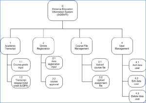
Functional decomposition is a systematic approach to breaking down complex systems or processes into smaller, more manageable subsystems or functions. In ECE & EEE projects, functional decomposition aids in modularizing system design, promoting reusability, and facilitating hierarchical design methodologies.
Steps in Functional Decomposition:
The process of functional decomposition typically involves the following steps:
- Identify System Functions: Identify the primary functions or tasks that the system must perform to achieve its objectives.
- Decompose Functions: Break down each primary function into sub-functions or tasks that represent specific actions or operations.
- Define Interfaces: Define interfaces between functions to establish communication, data exchange, and control flow between subsystems.
- Establish Hierarchy: Organize functions into a hierarchical structure, with higher-level functions representing broader system goals and lower-level functions representing detailed tasks or operations.
- Verify and Validate: Verify the correctness and completeness of the functional decomposition through reviews, simulations, or prototyping to ensure alignment with system requirements and objectives.
Integration of Flow Diagrams and Functional Decomposition:
Flow diagrams and functional decomposition are complementary methodologies that synergize to facilitate system design and development in ECE & EEE projects. Flow diagrams provide a macroscopic view of system flow and interaction, while functional decomposition offers a microscopic perspective on system functions and hierarchy. Together, these methodologies enable engineers to navigate the complexity of ECE & EEE projects, from conceptualization to implementation, with clarity and precision.
Case Study 1: Autonomous Drone Navigation System
In the creation of an autonomous drone navigation system, the integration of flow diagrams and functional decomposition is pivotal. Flow diagrams illustrate the flow of data and control signals among the drone’s sensors, actuators, and processing units, aiding in comprehending tasks like obstacle avoidance and waypoint navigation. Functional decomposition dissects complex navigation algorithms into modular functions, such as sensor fusion and path planning, facilitating the development of reusable software components and streamlining system integration. By synergizing flow diagrams and functional decomposition, the project team adopts a systematic approach to autonomous drone navigation, ensuring reliable and efficient operation across diverse environments.
Case Study 2: Smart Grid Energy Management System
In crafting a smart grid energy management system, the utilization of flow diagrams and functional decomposition proves essential. Flow diagrams depict the flow of electricity within the grid, from power generation to end-user appliances, facilitating analysis of energy consumption patterns and grid stability. Functional decomposition breaks down complex energy management algorithms into modular functions, like demand forecasting and load scheduling, enabling the creation of scalable and adaptable energy management solutions. By integrating flow diagrams and functional decomposition, the project team fosters efficient and sustainable energy management practices, advancing smart grid technology and promoting the adoption of renewable energy sources.
Case Study 3: Application of Flow Diagrams and Functional Decomposition in an ECE & EEE Project:
To illustrate the practical application of flow diagrams and functional decomposition, consider the design of a digital signal processing (DSP) system for audio processing. In this project, flow diagrams are used to visualize the signal flow, processing stages, and control logic of the DSP system. Functional decomposition is employed to modularize the system design, decomposing complex signal processing algorithms into smaller, reusable functions such as filtering, modulation, and demodulation. By integrating flow diagrams and functional decomposition, the project team achieves a structured and systematic approach to DSP system design, enhancing design clarity, modularity, and maintainability.
EEE Engineering Student Projects
Conclusion:
In conclusion, flow diagrams and functional decomposition are indispensable tools in the arsenal of ECE & EEE engineers, enabling them to tackle complex system design challenges with confidence and precision. By leveraging these methodologies, engineers can visualize system architecture, analyze process flow, and modularize design components, ultimately leading to the successful development and implementation of advanced ECE & EEE projects. As technology continues to evolve, the integration of flow diagrams and functional decomposition will remain essential for driving innovation, efficiency, and excellence in the field of electronics and electrical engineering.

